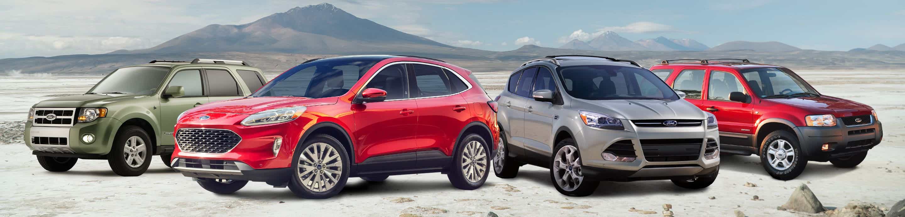

For those of you who have no idea what the subject line means, I have ordered parts off the 2008+ Mountaineer/Taurus X/Sable tail light configuration and will be actually committing to the project of converting my regular tail lights into some funky LED action.
Currently, this project is pretty common among Ranger and Corvette owners. The idea is a brighter, more reliable bulb that hopefully will not require replacing ever, while at the same time offering a pretty interesting appearance when the turn signals are activated or the brakes pressed. It's the same bulbs they use in the 2010+ Mustangs, which probably explains the crazy price hike of the part. It used to be $39 out of the dealership, but now it's $95. Times' a changin'.
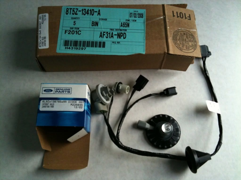
The parts I am receiving are:
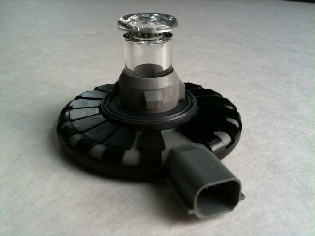
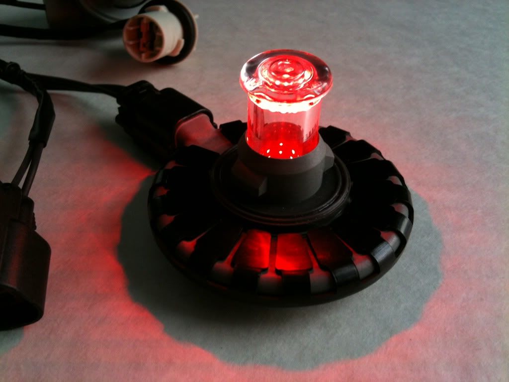
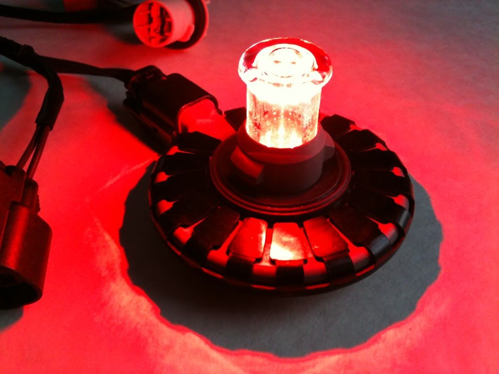
1. Two Sylvania/Osram L1224R (r for red) LED bulbs
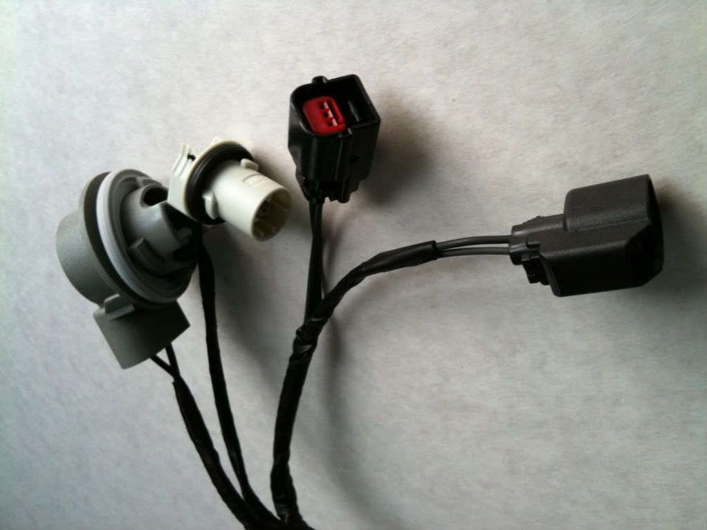
2. Two harnesses for the L1224R bulbs
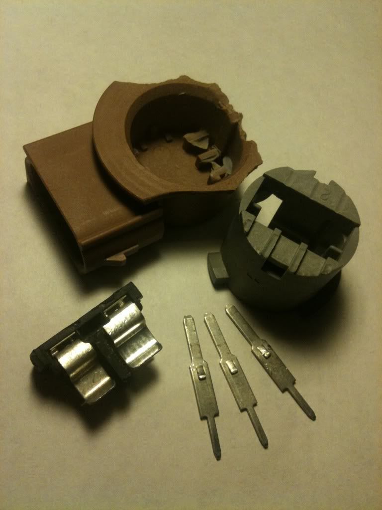
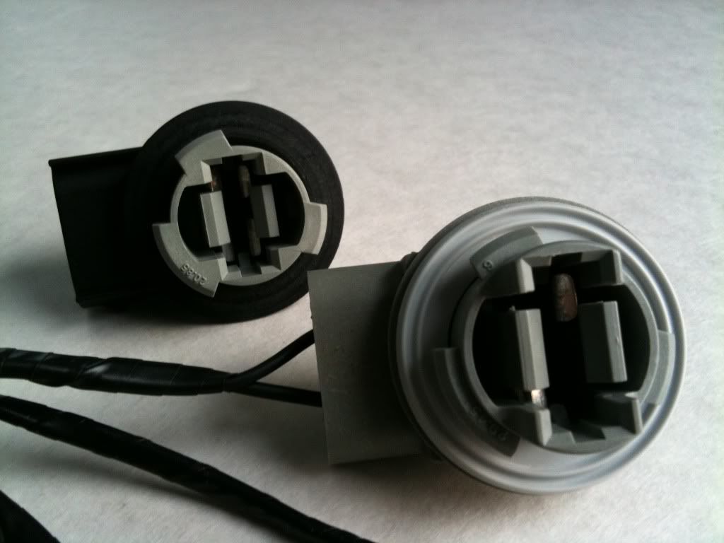
3. Two 4157 bulb sockets. The plastic piece that aligns with the tail light assembly to ensure an airtight fit will be the pieces required for the project.
Tools that I have:
- a small handsaw/blade
Tools that I don't have, and might need:
- a dremel
- glue
Patience is virtue. I'm pretty stoked. I will do periodic updates instead of one big slappity post.
Currently, this project is pretty common among Ranger and Corvette owners. The idea is a brighter, more reliable bulb that hopefully will not require replacing ever, while at the same time offering a pretty interesting appearance when the turn signals are activated or the brakes pressed. It's the same bulbs they use in the 2010+ Mustangs, which probably explains the crazy price hike of the part. It used to be $39 out of the dealership, but now it's $95. Times' a changin'.
The parts I am receiving are:
1. Two Sylvania/Osram L1224R (r for red) LED bulbs
2. Two harnesses for the L1224R bulbs
3. Two 4157 bulb sockets. The plastic piece that aligns with the tail light assembly to ensure an airtight fit will be the pieces required for the project.
Tools that I have:
- a small handsaw/blade
Tools that I don't have, and might need:
- a dremel
- glue
Patience is virtue. I'm pretty stoked. I will do periodic updates instead of one big slappity post.